
Page 361 - Planning and Design of Airports
P. 361
316 Airp o r t D e sign
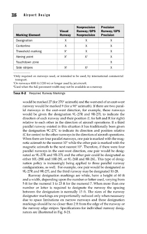
Nonprecision Precision
Visual Runway/GPS Runway/GPS
Marking Element Runway Nonprecision Precision
Designation X X X
Centerline X X X
Threshold marking X ∗ X X
Aiming point X † X † X
Touchdown zone X
Side stripes X ‡ X ‡ X
∗ Only required on runways used, or intended to be used, by international commercial
transport.
† On runways 4000 ft (1200 m) or longer used by jet aircraft.
‡ Used when the full pavement width may not be available as a runway.
TABLE 8-2 Required Runway Markings
would be marked 27 (for 270° azimuth) and the west end of an east-west
runway would be marked 9 (for a 90° azimuth). If there are two paral-
lel runways in the east-west direction, for example, these runways
would be given the designation 9L-27R and 9R-27L to indicate the
direction of each runway and their position (L for left and R for right)
relative to each other in the direction of aircraft operations. If a third
parallel runway existed in this situation it has traditionally been given
the designation 9C-27C to indicate its direction and position relative
(C for center) to the other runways in the direction of aircraft operations.
When there are four parallel runways, one pair is marked with the mag-
netic azimuth to the nearest 10° while the other pair is marked with the
magnetic azimuth to the next nearest 10°. Therefore, if there were four
parallel runways in the east-west direction, one pair would be desig-
nated as 9L-27R and 9R-27L and the other pair could be designated as
either 10L-28R and 10R-28L or 8L-26R and 8R-26L. This type of desig-
nation policy is increasingly being applied to three parallel runway
configurations, as well. For example, one pair would be designated as
9L-27R and 9R-27L and the third runway may be designated 10-28.
Runway designation markings are white, have a height of 60 ft
and a width, depending upon the number or letter used, varying from
5 ft for the numeral 1 to 23 ft for the numeral 7. When more than one
number or letter is required to designate the runway the spacing
between the designators is normally 15 ft. The sizes of the runway
designator markings are proportionally reduced only when necessary
due to space limitations on narrow runways and these designation
markings should be no closer than 2 ft from the edge of the runway or
the runway edge stripes. Specifications for individual runway desig-
nators are illustrated in Fig. 8-21.