
Page 38 - Plant design and economics for chemical engineers
P. 38
PROCESS DESIGN DEVELOPMENT 21
Stack
Exit gas to stack or power recovery
Ud
Cooler condensers
I
Bubble-cap
absorption
tower with
interplote
Platinu cooling
filter
+
Cxidotion
chamber
Mixing
chamber
B lwer T_
rt cry I- 17 60-65 wt. %
nitric acid
to storage
FIGURE 2-1
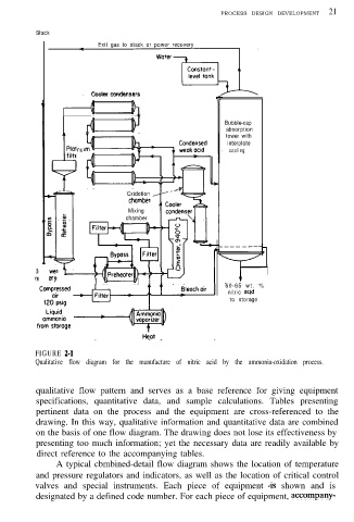
Qualitative flow diagram for the manufacture of nitric acid by the ammonia-oxidation process.
qualitative flow pattern and serves as a base reference for giving equipment
specifications, quantitative data, and sample calculations. Tables presenting
pertinent data on the process and the equipment are cross-referenced to the
drawing. In this way, qualitative information and quantitative data are combined
on the basis of one flow diagram. The drawing does not lose its effectiveness by
presenting too much information; yet the necessary data are readily available by
direct reference to the accompanying tables.
A typical cbmbined-detail flow diagram shows the location of temperature
and pressure regulators and indicators, as well as the location of critical control
valves and special instruments. Each piece of equipment 4s shown and is
designated by a defined code number. For each piece of equipment, accompany-