Page 217 - Plastics Engineering
P. 217

200                                Mechanical Behaviour of Composites

                                         x
                                     6.18  10-~ -3.87 x 10⁴  9.37 x  104
                                    -3.87 x        1.18 x      2.66 x     1  (N mm)-’
                                    -9.37 x 10⁻⁵   2.66 x 10⁻⁵  2.14 x 10⁻⁴
                                     1
                                                                                  -a12
                             E, = -                   1      G,,     1      v,,  = -,
                                              E, = -  = -
                                  all x  h’        a22 x  h’       wxh’           a1 1
                                         -a12
                                   vp = -
                                         a22
                             E,  = 24.26 GN/m2,   E, = 12.7 GN/m2
                            Gxy = 6.98 GN/m2,    vxy = 0.627,  up = 0.328

                        These values agree with those calculated above. Also,  for the applied force
                        N, = 50 x 2 = 100 N/mm.
                                                   [;?I
                                        [5]                  (=a[;]  -”)
                                             =a.


                           E,  = 2.061 x       cy = -1.291 x         yxy = -3.124 x
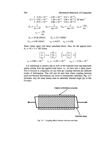
                          It is interesting to observe that as well as the expected axial and transverse
                        strains arising from the applied axial stress, a,,  we have also a shear strain.
                        This is because in composites we can often get coupling between the different
                        modes of  deformation. This will also be  seen later where coupling between
                        axial and flexural deformations can occur in unsymmetric laminates. Fig. 3.17
                        illustrates why the shear strains arise in uniaxially stressed single ply in this
                        Example.


                                                      Orlginal unidirectional composite


                                                                           Deformed shape

                                      Fig. 3.17  Coupling effects between extension and shear
   212   213   214   215   216   217   218   219   220   221   222