
Page 216 - Polymer-based Nanocomposites for Energy and Environmental Applications
P. 216
188 Polymer-based Nanocomposites for Energy and Environmental Applications
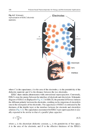
Fig. 6.2 Schematic Electrodes
representation of EDLC electrode
materials.
+
− − +
− − +
−
− − + +
+ − − + −
+
− + +
− +
− + − +
− + +
− +
+ Electrolyte
− Ions
Interface
where C is the capacitance, A is the area of the electrodes, ε is the permittivity of the
dielectric material, and D is the distance between the two electrodes.
EDLC share similar phenomenon with conventional supercapacitors. Conversely,
EDLCs store the energy between the interface of electrode and electrolyte. Schematic
diagram of EDLCs is displayed in Fig. 6.2. In EDLCS, the potential difference induces
the different polarity between the electrodes, resulting in the migration of electrolyte
ions to the micropores of the electrodes. The capacitance of EDLCs is estimated by the
thickness of the double layer at the interface between the electrode and electrolyte
solution (Fig. 6.2). The capacitance assessment for EDLC-type supercapacitors is usu-
ally expected to be similar to that of a parallel plate capacitor:
ε r ε o
C ¼ A (6.2)
D
where ε r is the electrolyte dielectric constant, ε o is the permittivity of free space,
A is the area of the electrode, and D is the effective thickness of the EDLCs