
Page 66 - Polymer-based Nanocomposites for Energy and Environmental Applications
P. 66
44 Polymer-based Nanocomposites for Energy and Environmental Applications
detrimental effect in degradation resistance, probably because of the degree of hydro-
philicity of the selected clay that produces a weak interphase with thepolymeric matrix.
The effect of nanoclay-enhanced epoxy matrix on Kevlar composites laminates
under low-velocity impact is studied by Reis et al. [35]. The laminates have been man-
ufactured with epoxy resin which is filled by 6 wt% of nanoclays and they show the
best performance in terms of elastic recuperation and penetration threshold. The oppo-
site tendency has been observed for the displacement at peak load. However, marginal
benefits have been found when it is compared with the results obtained for laminates
filled by 3% and 6% of nanoclays.
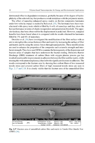
Drescher et al. [36] have investigated the modification of the fiber surface with an
aim to strengthen the contact between fiber and matrix by increasing the surface of fiber
and matrix and by using the atomic forces through nanoparticles. These modifications
are used to enhance the properties of the composite such as tensile strength and inter-
facialstrength.TheyhaveusedSEMtoexaminethehomogeneityofthedispersionsand
fracture areas of samples that have underwent the fracture testing. Dielectric-Barrier
Discharge (DBD) treatment of carbon fibers with oxygen plasma process gas has
resultedinnoticeableimprovementsinadhesionbetweenthefiberandthematrix,while
treatingthiswithammoniaplasma,ithasledtothesignificantdecreaseinadhesion.The
results correspond to the fracture area by showing free carbon fibers of low measured
tensile stress and covered carbon fibers of high measured tensile stress are seen in
Figs. 2.17 and 2.18. It is clearly visible that the fracture area of the unmodified fiber
Fig. 2.17 Fracture area of unmodified carbon fiber and matrix in Tensile Fiber Bundle Test
(TFBT) [36].