
Page 178 - Power Electronic Control in Electrical Systems
P. 178
//SYS21/F:/PEC/REVISES_10-11-01/075065126-CH005.3D ± 166 ± [153±176/24] 17.11.2001 10:15AM
166 Power semiconductor devices and converter hardware issues
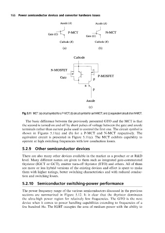
Fig.5.11 MCT:(a)circuitsymbolforaP-MCT;(b)circuitsymbolforanN-MCT;and(c)equivalentcircuitofanN-MCT.
The basic difference between the previously presented GTO and the MCT is that
the second is turned on and off by short pulses of voltage between the gate and anode
terminals rather than current pulse used to control the first one. The circuit symbol is
shown in Figures 5.11(a) and (b) for a P-MCT and N-MCT respectively. The
equivalent circuit is presented in Figure 5.11(c). The MCT exhibits capability to
operate at high switching frequencies with low conduction losses.
5.2.9 Other semiconductor devices
There are also many other devices available in the market as a product or at R&D
level. Many different names are given to them such as integrated gate-commutated
thyristor (IGCT or GCT), emitter turn-off thyristor (ETO) and others. All of them
are more or less hybrid versions of the existing devices and effort is spent to make
them with higher ratings, better switching characteristics and with reduced conduc-
tion and switching losses.
5.2.10 Semiconductor switching-power performance
The power frequency range of the various semiconductors discussed in the previous
sections are summarized in Figure 5.12. It is clear that the thyristor dominates
the ultra-high power region for relatively low frequencies. The GTO is the next
device when it comes to power handling capabilities extending to frequencies of a
few hundred Hz. The IGBT occupies the area of medium power with the ability to