
Page 351 - Power Electronic Control in Electrical Systems
P. 351
//SYS21/F:/PEC/REVISES_10-11-01/075065126-CH008.3D ± 335 ± [290±372/83] 17.11.2001 10:29AM
Power electronic control in electrical systems 335
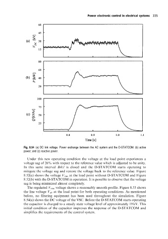
Fig. 8.54 (a) DC link voltage. Power exchange between the AC system and the D-STATCOM: (b) active
power; and (c) reactive power.
Under this new operating condition the voltage at the load point experiences a
voltage sag of 26% with respect to the reference value which is adjusted to be unity.
In this same interval Brk1 is closed and the D-STATCOM starts operating to
mitigate the voltage sag and restore the voltage back to the reference value. Figure
8.52(a) shows the voltage V rms at the load point without D-STATCOM and Figure
8.52(b) with the D-STATCOM in operation. It is possible to observe that the voltage
sag is being minimized almost completely.
The regulated V rms voltage shows a reasonably smooth profile. Figure 8.53 shows
the line voltage V ab at the load point for both operating conditions. As mentioned
before, no filtering equipment has been used throughout the simulation. Figure
8.54(a) shows the DC voltage of the VSC. Before the D-STATCOM starts operating
the capacitor is charged to a steady state voltage level of approximately 19 kV. This
initial condition of the capacitor improves the response of the D-STATCOM and
simplifies the requirements of the control system.