
Page 353 - Power Electronic Control in Electrical Systems
P. 353
//SYS21/F:/PEC/REVISES_10-11-01/075065126-CH008.3D ± 337 ± [290±372/83] 17.11.2001 10:29AM
Power electronic control in electrical systems 337
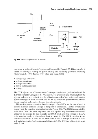
Fig. 8.55 Schematic representation ofthe DVR.
connected in series with the AC system, as illustrated in Figure 8.55. This controller is
suited for solving a variety of power quality and reliability problems including
(Osborne et al., 1995; Taylor, 1995; Chan and Kara, 1998):
. voltage sags and swells
. voltage unbalances
. voltage harmonics
. power factor correction
. outages.
The DVR injects a set of three-phase AC voltages in series and synchronized with the
distribution feeder voltages of the AC system. The amplitude and phase angle of the
injected voltages are variable thereby allowing control of the active and reactive
power exchanges between the DVR and the AC system within predetermined positive
(power supply), and negative (power absorption) limits.
This section presents the time domain analysis of the DVR for the case when it is
used to maintain constant voltage at the point of connection. The test system used
to carry out the transient studies is shown in Figure 8.56. The DVR is connected in
series with Load 1 in order to protect this load against any disturbance that could
appear in the system. In this example, the DVR must keep the voltage at Load 1
point constant under a three-phase fault at point A. The DVR coupling trans-
former is connected in delta in the DVR side. It has a leakage reactance of 10%
and unity turns ratio (no booster capabilities exist). The DC link voltage is assumed
to be 2.5 kV.