
Page 397 - Power Electronic Control in Electrical Systems
P. 397
//SYS21/F:/PEC/REVISES_10-11-01/075065126-CH009.3D ± 376 ± [373±406/34] 17.11.2001 10:33AM
376 Examples, problems and exercises
(100 j0) j0:1 100e j36:87 106:3e j4:32 V. Note that the supply voltage E has
to be higher to achieve the same load voltage when the power-factor is lagging. The
load angle is d 4:32 and S VI 100 100e j36:87 8000 j6000 VA. Thus
S 10 kVA, P 8 kW and Q 6 kVAr (absorbed).
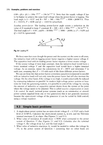
Leading power-factor. The leading power-factor angle causes a reduction in the
value of E required to keep V constant: E 100 j0:1 100e j36:87 94:3e j4:86 V.
The load angle is d 4:86 , and S 10 000e j36:87 8000 j6000; i.e. P 8 kW and
Q 6 kVAr (generated).
Fig. 9.4 Leading PF.
We have seen that even though the power and the current are the same in all cases,
the inductive load with its lagging power factor requires a higher source voltage E.
The capacitive load with its leading power factor requires a lower source voltage.
If the source voltage E were kept constant, then the inductive load would have a
lower terminal voltage V and the capacitive load would have a higher terminal
voltage. As an exercise, repeat the calculations for E 100 V and determine V in
each case, assuming that Z 1
with each of the three different power-factors.
We can see from this that power-factor correction capacitors (connected in parallel
with an inductive load) will not only raise the power factor but will also increase the
voltage. On the other hand, if the voltage is too high, it could conceivably be reduced
by connecting inductors in parallel. In modern high-voltage power systems at loca-
tions far from the generating stations, it is possible to control the voltage by varying
the amount of inductive or capacitive current drawn from the system at the point
where the voltage needs to be adjusted. This is called reactive compensation or static
VAr control. In small, isolated power systems (such as an automotive or aircraft
power system supplied from one or two generators) this is not generally necessary
because the open-circuit voltage of the generator E can be varied by field control,
using a voltage regulator.
9.3 Simple basic problems
1. A single-phase power system has an open-circuit voltage E 6:35 kV and a fault
level of 16 MVA. Calculate the short-circuit current I sc in kA, and the The  venin
internal reactance X s in ohms. (See Figures 2.1 and 9.1).
2. What value of resistance R would draw 1.5 MW when connected to the power
system of Question 1? (See Figures 2.1 and 9.2). Calculate also the terminal
voltage V, the voltage drop X s I, and the load angle d.
3. What value of inductive reactance X L would be needed to reduce the voltage by
3% in the power system of Question 1 (assuming that no other loads are