
Page 402 - Power Electronic Control in Electrical Systems
P. 402
//SYS21/F:/PEC/REVISES_10-11-01/075065126-CH009.3D ± 381 ± [373±406/34] 17.11.2001 10:33AM
Power electronic control in electrical systems 381
(iii) the sending end voltage when the load is 900 MVA with a lagging power
factor of 0.88;
(iv) the transmission angle d in degrees;
(v) the sending-end current;
(vi) the power and reactive power at the sending end; and
(vii) draw the phasor diagram showing the phase voltage and current at both
ends.
o` 0:60
/km and oc 50 10 6 S/km
p p p
6
(i) Z o (`/c) (o`/oc) (0:60/(50 10 )) 109:545
p p
6
(ii) b (o` oc) (0:60 50 10 ) 0:005477 radians/km
0:31382 /km
y ba 0:005477 14:8 0:08106 radians 4:64456
(iii) E s V r cos y jZ o I r sin y
From Question 6, I r 1:50613e j28:3576 kA
p
\E s (345/ 3)cos 4:64456 j109:545 sin 4:64456 1:50613e j28:3576 kV
198:532 13:35984 e j(90 28:3576)
198:532 6:34556 j11:757 204:878 j11:757
205:214e j3:2843 kV l n, i:e: 355:442 kV line line
p
Thus if V r 1:0p:u, E s 205:215/(345/ 3) 1:0303 p:u:
(iv) Transmission angle d 3:2843 .
Check the power transmission: Z o sin y 109:545 sin 4:64456 8:87031
p
P (205:215 345 3/8:87031) sin 3:2843 264:0 MW/phase.
(v) I s j(V r /Z o ) sin y I r cos y
p
j(345/ 3)/109:545 sin 4:64456 1:50613e j28:3576 cos 4:64456
1:32104 j0:56579 kA 1:43710e j23:1850 kA
(vi) P s jQ s E s I 3 205:214e j3:2843 1:43710e j23:1850
s
792:0 j394:3 MVA.
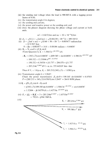
(vii)
Fig. 9.5