Page 404 - Power Electronic Control in Electrical Systems
P. 404

//SYS21/F:/PEC/REVISES_10-11-01/075065126-CH009.3D ± 383 ± [373±406/34] 17.11.2001 10:33AM


                                                            Power electronic control in electrical systems 383

                              Electrical length y ˆ phase angle between E s and E r at the surge-impedance
                              load.
                                     jd              P r   jQ r  sin y
                          (ii) E s ˆ E s e ˆ V r cos y ‡ jZ 0
                                                       V r
                              . . . use this to derive
                                                           2
                                                         E (cos d   cos y)
                                            Q s ˆ Q r ˆ    s
                                                             Z 0 sin y
                                                              2        2
                          (iii) (a) Surge impedance load P 0 ˆ V /Z 0 ˆ 500 /50:4 ˆ 4960 MW P max ˆ
                                                              0
                                 P 0 / sin y ˆ 4960/ sin 8:7 ˆ 32 793 MW.

                              (b) P/P 0 ˆ sin d/sin y ˆ 0:47, so sin d ˆ 0:47   sin 8:7 ,i.e. d ˆ 4:07674 .


                                                 2
                                 Q s ˆ Q r ˆ 500 ( cos 4:07674   cos 8:7 )/(50:4 sin 8:7 )


                                 ˆ 294:3 MVAr ± absorbing at both ends.
                      11.  (i) What are the functions of reactive compensation applied to electrical trans-
                              mission systems?
                          (ii) What are the differences between passive and active compensators? Give
                              examples of both.
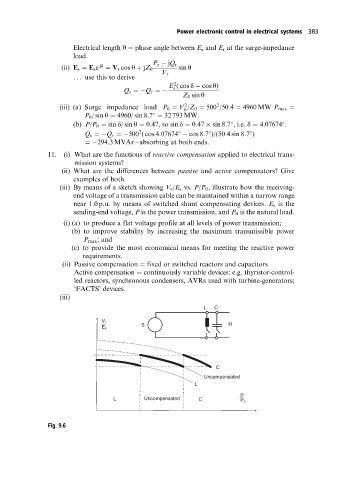
                          (iii) By means of a sketch showing V r /E s vs. P/P 0 , illustrate how the receiving-
                              end voltage of a transmission cable can be maintained within a narrow range
                              near 1.0 p.u. by means of switched shunt compensating devices. E s is the
                              sending-end voltage, P is the power transmission, and P 0 is the natural load.
                           (i) (a) to produce a flat voltage profile at all levels of power transmission;
                             (b) to improve stability by increasing the maximum transmissible power
                                 P max ; and
                             (c) to provide the most economical means for meeting the reactive power
                                requirements.
                          (ii) Passive compensation ˆ fixed or switched reactors and capacitors
                              Active compensation ˆ continuously variable devices: e.g. thyristor-control-
                              led reactors, synchronous condensers, AVRs used with turbine-generators;
                              `FACTS'devices.
                          (iii)
                                                                    L  C

                                      V r                                  R
                                                 S
                                      E s


                                                                       C
                                                                    Uncompensated
                                                                 L
                                                                              P
                                                  Uncompensated
                                         L        Uncompensated   C           P o

                      Fig. 9.6
   399   400   401   402   403   404   405   406   407   408   409