
Page 88 - Power Electronic Control in Electrical Systems
P. 88
//SYS21/F:/PEC/REVISES_10-11-01/075065126-CH002.3D ± 77 ± [31±81/51] 17.11.2001 9:49AM
Power electronic control in electrical systems 77
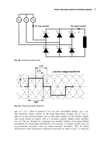
Fig. 2.49 Three-phase rectifier circuit.
Fig. 2.50 Three-phase rectifier waveforms.
and jI 7 j I 1 /7. Thus in general if h is an odd non-triplen integer, jI h j I 1 /h.
The harmonic orders present in the ideal three-phase rectifier are h kq 1,
where kis any positive integer and q is the pulse number of the rectifier circuit.
The circuit shown in Figure 2.49 is a six-pulse rectifier. Higher pulse numbers
(e.g. 12, 24) are obtained by supplying two parallel rectifiers from phase-shifted
secondaries of a three-phase transformer. For example, a 12-pulse rectifier uses one
wye-connected secondary and one delta-connected secondary. The 30 phase
shift between these secondaries eliminates harmonics of orders 5 and 7, so that the