
Page 367 - Power Electronics Handbook
P. 367
Power supplies 357
Performance factors used in the measurement of power supplies include:
(i) Line regulation, the variation in the load voltage as the input voltage
changes.
(ii) Load regulation, where the load voltage fluctuates as the load current
changes.
(iii) Temperature regulation, resulting in changes in output voltage due to
variations in temperature, primarily due to temperature effects on
components used within the power supply.
(iv) Ripple and noise, caused by switching effects within the power supply
and insufficient filtering at the output.
Power supplies usually provide two forms of protection for the load,
overvoltage and overcurrent. Overvoltage protection is normally achieved
by sensing the power supply output voltage and applying a short-circuit
across the power supply output lines when this voltage exceeds a preset
value. Thyristor crowbar circuits are used for this since the semiconductor
switch can be made to operate within a fraction of a second, so preventing
damage to the load. Once the crowbar has operated, overcurrent circuitry
within the power supply comes into play, as described below.
Overcurrent protection is required not only to guard the load from
excessive currents under certain fault conditions, but also to protect the
power supply from damage. It is achieved by sensing the load current and
feeding this back to the voltage control section within the supply, so that
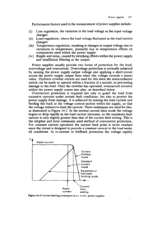
the voltage reduces to limit the current. Three techniques are used for this,
as illustrated in Figure 14.2. In the normal current limit mode the voltage
begins to drop rapidly as the load current increases, so the maximum fault
current is only slightly greater than that of the current limit setting. This is
the simplest and most commonly used method of overcurrent protection.
For constant current operation the current limit point is never reached
since the circuit is designed to provide a constant current to the load under
all conditions. In re-entrant or foldback protection the voltage rapidly
I ‘Current
Rated limit
current setting
Figure 14.2 Current-limiting techniques in ax. to d.c. power supplies