
Page 366 - Power Electronics Handbook
P. 366
356 Power semiconductor circuit applications
phase control of thyristors or a triac is commonly used. The regulated
voltage is then rectified and filtered to give the d.c. output. Voltage
regulation is used to enable the operator to vary the magnitude of the
output voltage, but it also provides a control mechanism for keeping the
voltage constant under changing load current or input voltage and a
method for limiting the current under fault conditions.
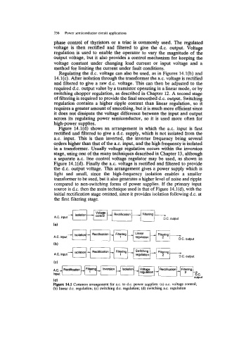
Regulating the d.c. voltage can also be used, as in Figures 14.l(b) and
14.1(c). After isolation through the transformer the a.c. voltage is rectified
and filtered to give a raw d.c. voltage. This can then be adjusted to the
required d.c. output value by a transistor operating in a linear mode, or by
switching chopper regulation, as described in Chapter 12. A second stage
of filtering is required to provide the final smoothed d.c. output. Switching
regulation contains a higher ripple content than linear regulation, so it
requires a greater amount of smoothing, but it is much more efficient since
it does not dissipate the voltage difference between the input and output
across its regulating power semiconductor, so it is used more often for
high-power supplies.
Figure 14.l(d) shows an arrangement in which the a.c. input is first
rectified and filtered to give a d.c. supply, which is not isolated from the
a.c. input. This is then inverted, the inverter frequency being several
orders higher than that of the a.c. input, and the high frequency is isolated
in a transformer. Usually voltage regulation occurs within the inversion
stage, using one of the many techniques described in Chapter 13, although
a separate a.c. line control voltage regulator may be used, as shown in
Figure 14.1(d). Finally the a.c. voltage is rectified and filtered to provide
the d.c. output voltage. This arrangement gives a power supply which is
light and small, since the high-frequency isolation enables a smaller
transformer to be used, but it also generates a higher level of noise and ripple
compared to non-switching forms of power supplies. If the primary input
source is d.c. then the main technique used is that of Figure 14.1(d), with the
initial rectification stage omitted, since it provides isolation following d.c. at
the first filtering stage.
Filtering
A.C. input
Filtering
A.C. input * L.C. output
(b)
A.C. input
..
Figure 14.1 Common arrangement for a.c. to d.c. power supplies: (a) ax. voltage control;
(b) linear d.c. regulation; (c) switching d.c. regulation; (d) switching a.c. regulation