
Page 361 - Power Electronics Handbook
P. 361
Inverter control circuits 35 1
Frequency Harmonic Voltage
control mntrol control
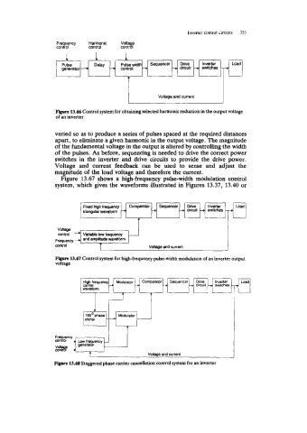
Pulse Delay pulsewidth Sequencer Drive lnvyler Load
generator --+ 3 control -+ + circuit --. swtches 3
Voltage and current
Figure 13.66 Control system for obtaining selected harmonic reduction in the output voltage
of an inverter
varied so as to produce a series of pulses spaced at the required distances
apart, to eliminate a given harmonic in the output voltage. The magnitude
of the fundamental voltage in the output is altered by controlling the width
of the pulses. As before, sequencing is needed to drive the correct power
switches in the inverter and drive circuits to provide the drive power.
Voltage and current feedback can be used to sense and adjust the
magnitude of the load voltage and therefore the current.
Figure 13.67 shows a high-frequency pulse-width modulation control
system, which gives the waveforms illustrated in Figures 13.37, 13.40 or
Frequency 4 mr I
control and Wwok Voltape and current
Figure 13.67 Control system for high-frequency pulse-width modulation of an inverter output
voltage
Sequencer We. Inverter
circuit 1 switches