
Page 358 - Power Electronics Handbook
P. 358
348 D.C. link frequency changers
It is seen from the waveforms that the voltage-fed inverter is not suitable
for operating into capacitive loads, due to the high spikes of current, whilst
the current-fed inverter results in high-voltage transients, when operating
into inductive loads or where the load gives a high impedance to harmonic
currents. The current-fed inverter is ideal when the load presents a low
impedance to harmonic currents and is close to unity power factor, for
example a tuned circuit used for induction heating where a large capacitor
is connected across the heating coil. In these instances the inverter
operates at substantial constant frequency and the load voltage is
sinusoidal, as shown in Figure 13.62. The current through the inverter
switches is still square and these provide the energy to compensate for
resonant losses in the tuned load.
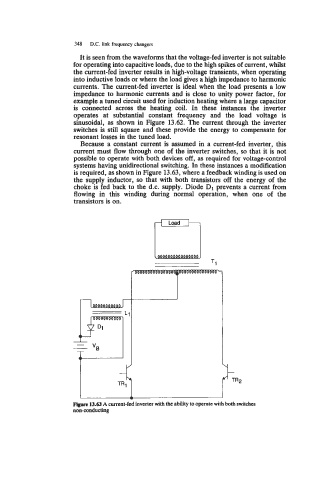
Because a constant current is assumed in a current-fed inverter, this
current must flow through one of the inverter switches, so that it is not
possible to operate with both devices off, as required for voltage-control
systems having unidirectional switching. In these instances a modification
is required, as shown in Figure 13.63, where a feedback winding is used on
the supply inductor, so that with both transistors off the energy of the
choke is fed back to the d.c. supply. Diode D1 prevents a current from
flowing in this winding during normal operation, when one of the
transistors is on.
-I c
I
Figure 13.63 A current-fed inverter with the ability to operate with both switches
non-conducting