
Page 359 - Power Electronics Handbook
P. 359
The current-fed inverter 349
L1
q
TH3
D1
"B
-
I I
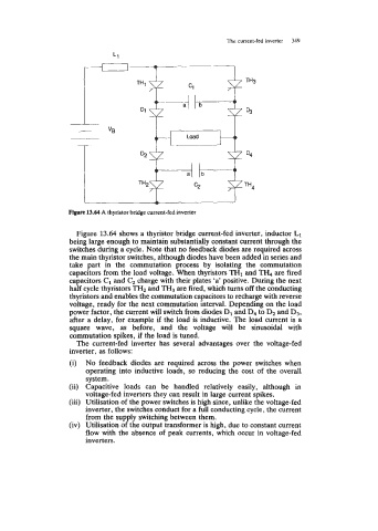
Figure 13.64 A thyristor bridge current-fed inverter
Figure 13.64 shows a thyristor bridge current-fed inverter, inductor L1
being large enough to maintain substantially constant current through the
switches during a cycle. Note that no feedback diodes are required across
the main thyristor switches, although diodes have been added in series and
take part in the commutation process by isolating the commutation
capacitors from the load voltage. When thyristors TH1 and TH, are fired
capacitors C1 and C, charge with their plates 'a' positive. During the next
half cycle thyristors TH2 and TH3 are fired, which turns off the conducting
thyristors and enables the commutation capacitors to recharge with reverse
voltage, ready for the next commutation interval. Depending on the load
power factor, the current will switch from diodes D1 and D4 to D2 and D3,
after a delay, for example if the load is inductive. The load current is a
square wave, as before, and the voltage will be sinusoidal with
commutation spikes, if the load is tuned.
The current-fed inverter has several advantages over the voltage-fed
inverter, as follows:
(i) No feedback diodes are required across the power switches when
operating into inductive loads, so reducing the cost of the overall
system.
(ii) Capacitive loads can be handled relatively easily, although in
voltage-fed inverters they can result in large current spikes.
(iii) Utilisation of the power switches is high since, unlike the voltage-fed
inverter, the switches conduct for a full conducting cycle, the current
from the supply switching between them.
(iv) Utilisation of the output transformer is high, due to constant current
flow with the absence of peak currents, which occur in voltage-fed
inverters.