
Page 357 - Power Electronics Handbook
P. 357
The current-fed inverter 347
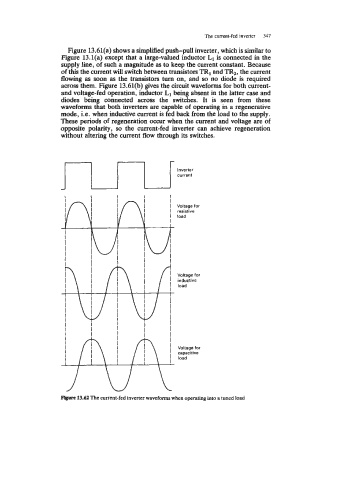
Figure 13.61(a) shows a simplified push-pull inverter, which is similar to
Figure 13.l(a) except that a large-valued inductor L1 is connected in the
supply line, of such a magnitude as to keep the current constant. Because
of this the current will switch between transistors TRI and TR2, the current
flowing as soon as the transistors turn on, and so no diode is required
across them. Figure 13.61(b) gives the circuit waveforms €or both current-
and voltage-fed operation, inductor L1 being absent in the latter case and
diodes being connected across the switches. It is seen from these
waveforms that both inverters are capable of operating in a regenerative
mode, i.e. when inductive current is fed back from the load to the supply.
These periods of regeneration occur when the current and voltage are of
opposite polarity, so the current-fed inverter can achieve regeneration
without altering the current flow through its switches.
Inverter
current
Voltage for
resistive
load
Voltage for
inductive
load
Voltage for
capacirive
load
Figure 13.62 The current-fed inverter waveforms when operating into a tuned load