
Page 360 - Power Electronics Handbook
P. 360
350 D.C. link frequency changers
(v) The RFI generated in a current-fed inverter is much lower than that
in voltage-fed inverters, since RFI is essentially generated by
changing currents and in a current-fed inverter the current is
substantially constant.
(vi) The current drawn from the supply in a current-fed inverter is much
smoother than that in a voltage-fed inverter, so that the filtering
requirements are also much less.
In spite of some of the advantages of current-fed inverters, voltage-fed
inverters continue to be used, since they are more versatile in a variety of
applications, and they are easier to control.
13.6 Inverter control circuits
A variety of control circuits exist for inverters, dependent on the system
used to vary the output voltage and the inverter configuration. All these
will consist of the power semiconductor drive circuit and a form of
sequencing to turn the devices on at the appropriate instances in the cycle,
usually incorporated into a single integrated circuit.
Figure 12.23 illustrated a method of mark-to-space control of the output
voltage, using a sawtooth waveform and a pedestal reference, and this was
incorporated into a control circuit for a chopper in Figure 12.24. The same
technique can be used to provide mark-to-space control within an inverter,
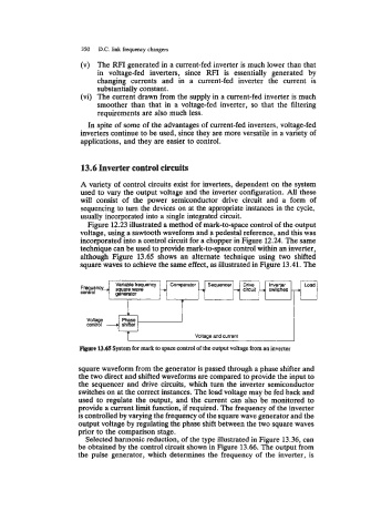
although Figure 13.65 shows an alternate technique using two shifted
square waves to achieve the same effect, as illustrated in Figure 13.41. The
Variable frequency Comparator Sequencer Drive Inverter
Fr~enc)L, square wave -+ --+ -D circuit -+ switches
control generator
Figure 13.65 System for mark to space control of the output voltage from an inverter
square waveform from the generator is passed through a phase shifter and
the two direct and shifted waveforms are compared to provide the input to
the sequencer and drive circuits, which turn the inverter semiconductor
switches on at the correct instances. The load voltage may be fed back and
used to regulate the output, and the current can also be monitored to
provide a current limit function, if required. The frequency of the inverter
is controlled by varying the frequency of the square wave generator and the
output voltage by regulating the phase shift between the two square waves
prior to the comparison stage.
Selected harmonic reduction, of the type illustrated in Figure 13.36, can
be obtained by the control circuit shown in Figure 13.66. The output from
the pulse generator, which determines the frequency of the inverter, is