
Page 355 - Power Electronics Handbook
P. 355
The current-fed inverter 345
PCOM I I
5.0 -
C
0
Yz 4.0-
z
m
c
E 3.0-
0
0
L
g 2.0-
v)
v)
-
0
t: 1.0-
2
5000 10 000 15 000 20 000 25 000 30 OOO 35 000 40 000 45 000 50 On0
Supply voltage x peak load current (VB . IL(pk))
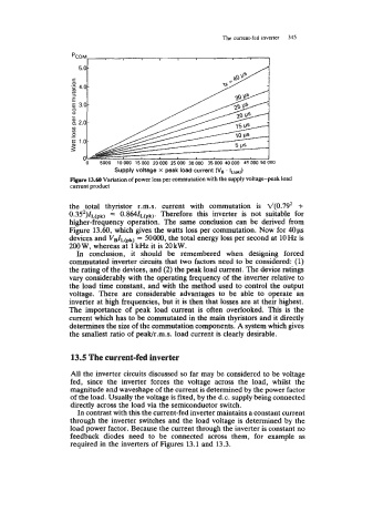
Figure 13.60 Variation of power loss per commutation with the supply voltage-peak load
current product
the total thyristor r.m.s. current with commutation is d(0.79’ +
0.352)lypk, = 0.864ZL(pk). Therefore this inverter is not suitable for
higher-frequency operation. The same conclusion can be derived from
Figure 13.60, which gives the watts loss per commutation. Now for 40~
devices and v&(pk) = 50000, the total energy loss per second at loHz is
200 W, whereas at 1 kHz it is 20 kW.
In conclusion, it should be remembered when designing forced
commutated inverter circuits that two factors need to be considered: (1)
the rating of the devices, and (2) the peak load current. The device ratings
vary considerably with the operating frequency of the inverter relative to
the load time constant, and with the method used to control the output
voltage. There are considerable advantages to be able to operate an
inverter at high frequencies, but it is then that losses are at their highest.
The importance of peak load current is often overlooked. This is the
current which has to be commutated in the main thyristors and it directly
determines the size of the commutation components. A system which gives
the smallest ratio of peak/r.m.s. load current is clearly desirable.
13.5 The current-fed inverter
All the inverter circuits discussed so far may be considered to be voltage
fed, since the inverter forces the voltage across the load, whilst the
magnitude and waveshape of the current is determined by the power factor
of the load. Usually the voltage is fixed, by the d.c. supply being connected
directly across the load via the semiconductor switch.
In contrast with this the current-fed inverter maintains a constant current
through the inverter switches and the load voltage is determined by the
load power factor. Because the current through the inverter is constant no
feedback diodes need to be connected across them, for example as
required in the inverters of Figures 13.1 and 13.3.