
Page 351 - Power Electronics Handbook
P. 351
Design of inverter circuits 34 I
2nfL. Each harmonic must be treated individually and the harmonic
composition of the wave changes with pulse-width control. As expected,
there is an increase in power factor as frequency is reduced and load
resistance has a greater effect. The curves converge at low voltages where
the harmonics become a greater percentage of the fundamental. This also
accounts for the decrease, with reduction in pulse width, at any frequency.
13.4.2 Commutation effects on inverter design
In this section a typical thyristor inverter, including all commutation
components, will be considered, and the method of specifying the
commutation components and their effect on the device ratings will be
determined. Although these will be determined by the actual commutation
method selected, the technique used in their evaluation is common to all
circuits.
$..
TH31
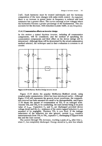
Figure 13.55 McMurray-Bedford bridge inverter circuit
Figure 13.55 shows the popular McMurray-Bedford circuit, using
coupled-pulse commutation, which has been introduced earlier. Although
Figure 13.49 still represents the general circuit waveforms, the commuta-
tion interval has been assumed too small to be distinguishable, and Figure
13.56 shows the instant of commutation of TH3 to an enlarged scale.
Assume TH3 and TH, to be conducting, the load current being at its peak
value of zL(pk). Capacitors C3 and C, are discharged provided device
voltage drops and the d.c. resistance of the centre-tapped inductors Lo are
assumed to be negligible. Thyristor TH1 is now fired. If the leakage
inductance of the inductors are also ignored, current ZL(pk) transfers
instantaneously from TH3 to TH1, capacitor C1 discharging to support both
this and the load current.
The current through TH1 increases, reaching a peak of lpk after time tl,
when C1 has completely discharged. Energy stored in now free-wheels