Page 350 - Power Electronics Handbook
P. 350

340   D.C. link frequency changers
                         1 .o     I      I     I      I     I      I     1      I      I
                            -
                         0.9
                         0.8  -
                       c.
                       C    -
                       g  0.7
                       a
                       0  . 0.6 -
                       v!   -
                       4  0.5
                       U
                       p 0.4-
                       0
                       5 0.3-
                       U
                       0    -
                       6 0.2
                            -
                         0.1
                                 Ib      I     I      I      I     I      I     I
                           OO           20     30    40     50    60     70     80    90
                                                 Fundamental as  % of d.c.
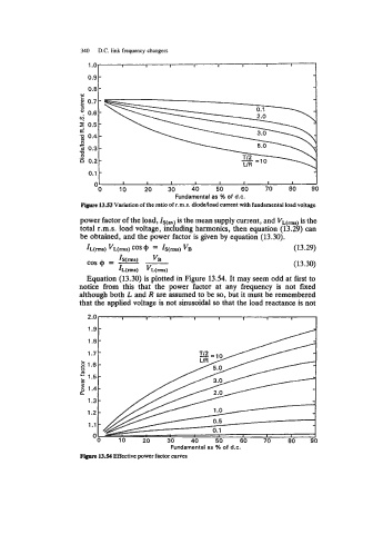
                       Ffye 13.53 Variation of the ratio of t.m.s. dioddoad current with fundamental load voltage
                       power factor of the load,   is the mean supply current, and VL(-)  is the
                       total r.m.s.  load voltage, inciuding harmonics, then equation (13.29) can
                       be obtained, and the power factor is given by equation (13.30).
                        IL(rms) vL(rms)  COS 4)  = IS(rms) VB                    (13.29)
                         cos 4)  = - -                                           (13.30)
                                          VB
                                 IS(rms)
                                 IL(rms)  VL(rmS)
                         Equation (13.30) is plotted in Figure 13.54. It may seem odd at first to
                       notice  from  this  that  the  power  factor  at  any  frequency  is  not  fixed
                      although both L and R are assumed to be so,  but it must be remembered
                      that the applied voltage is not sinusoidal so  that the load reactance is not

                         2.0      I      I     I      I     I      8      I     I
                            -
                         1.9
                            -
                         1.8
                            -
                         1.7'


                                               Fundamental as 46 of d.c.
                       Figure 13.54 Effective power factor curves
   345   346   347   348   349   350   351   352   353   354   355