
Page 369 - Power Electronics Handbook
P. 369
Power supplies 359
The a.c. supply and rectification shown in Figure 14.1 can be single
phase or three phase, and the filtering used can consist of several types,
capacitor input filters being illustrated in Figure 14.3. This circuit, as
applied to a mercury arc rectifier, has been extensively analysed by O.H.
Schade (Pruc. IRE, July 1943) and his design curves, one of which is
illustrated in Figure 14.4, are still used today. The series resistor Rs is
usually that of the transformer winding, the rectifier resistance and any
external resistance added to limit the surge current caused by the charging
effect of the capacitors in the filter.
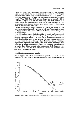
Figure 14.4 gives the magnitude of the d.c. output and Figure 14.5 the
load ripple voltage. Generally, the value of oRLoADC is chosen to operate
on the flat portion of the curves of Figure 14.4 and to reduce the ripple to
the desired value.
At high-load currents a choke input filter is usually preferred, since it
gives better smoothing without needing a large value of capacitance
carrying high ripple current. This filter can be obtained by replacing the
series resistor Rs in Figure 14.3 by a choke. For applications which require
very smooth supplies even this single-stage filter is inadequate, resulting in
large-valued capacitors and chokes, and multi-section filtering is then
preferred, as shown in Figure 14.6. Figure 14.7 illustrates the attenuation
curves for these filters, where fr is the fundamental ripple frequency, and
from this it is seen that high attenuation factors are obtained more
effectively by multistage filters.
14.2.1 Unintemiptabk power supplies
Power supplies are often required which provide a.c. at the mains
frequency of 50 Hz or 60 Hz once the mains fails. They are usually used to
loor
c - 10
In
P
- 5
a
.- 2
,:
L 3
vjl
?
a 1
Figure 14.5 Ripple voltage curves for full-wave rectifier circuits with capacitor input filters