
Page 374 - Power Electronics Handbook
P. 374
364 Power semiconductor circuit applications
most cases the control system must be rated to withstand the peak
overload expected instead of the usual full-load value.
(ii) Inability of a power semiconductor system to regenerate unless
special circuit modifications are included, such as double-bridge
controllers. A motor-generator set, on the other hand, can readily
pass energy in either direction.
(iii) Low power factors in drives which use phase angle control. As has
been illustrated in previous chapters the load power factor is
approximately proportional to the delay in the turn-on of the power
semiconductor within an a.c. half cycle, and the power factor will
therefore be poor at low speeds, when the voltage is low and the
delay angle is therefore large.
(iv) Generated harmonics in systems where large voltages are switched,
due to the very fast operating time of the power semiconductor.
These harmonics cause radio frequency interference which must be
suppressed.
14.3.1 Elements of electrical machines
Machines fall into two groups, motors and generators. To explain the
difference between them it is necessary to discuss the operating principles
of an elementary machine, as in Figure 14.11. The essential requirement
for production of magnetic force is interaction of two magnetic fields. The
force of attraction and repulsion between two bar magnets is well known, a
similar force resulting if one or both magnets are replaced by a
current-carrying conductor.
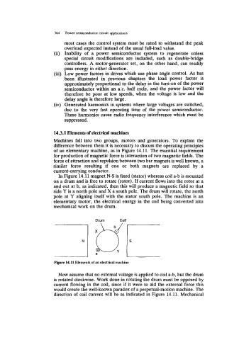
In Figure 14.11 magnet N-S is fixed (stator) whereas coil a-b is mounted
on a drum and is free to rotate (rotor). If current flows into the rotor at a
and out at b, as indicated, then this will produce a magnetic field so that
side Y is a north pole and X a south pole. The drum will rotate, the north
pole at Y aligning itself with the stator south pole. The machine is an
elementary motor, the electrical energy in the coil being converted into
mechanical work on the drum.
Drum Coil
Figure 14.11 Elements of an electrical machine
Now assume that no external voltage is applied to coil a-b, but the drum
is rotated clockwise. Work done in rotating the drum must be opposed by
current flowing in the coil, since if it were to aid the external force this
would create the well-known paradox of a perpetual-motion machine. The
direction of coil current will be as indicated in Figure 14.11. Mechanical