
Page 375 - Power Electronics Handbook
P. 375
Electrical machine control 365
work is done in overcoming the repulsion between similar poles on stator
and rotor, and this is converted to electrical energy in the coil, so that the
machine is a generator.
It is clear that the construction of a motor and generator for a given type
are very similar, it is only the terms of reference which differ. For a motor
energy input is electrical and output is mechanical, whilst for a generator
mechanical input energy is converted to an electrical output.
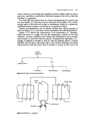
Motors and generators can be further divided into various groups as
shown in Figure 14.12, and these will be discussed in the following sections.
Figure 14.13 shows the construction of an elementary d.c. machine,
where the rotor is a single coil and the commutator consists of two half
cylinders. During a complete coil rotation the commutators are in contact
with brushes A and B for half the period. During motor operation a d.c.
voltage is applied to brushes A and B, with the polarity shown. Current
will flow up coil side a and down side b, this current forming rotor poles
which interact with the stator flux to produce a torque on the coil in an
Motor1
generator
D.C. A.C.
(commutator) 1
I I
Induction Synchronous Commutator
Figure 14.12 Types of electrical machines
Rotor
coil
a b
I
Commutator
Brushes
A B
-k -
Figure 14.13 Basic d.c. machine