
Page 376 - Power Electronics Handbook
P. 376
366 Power semiconductor circuit applications
(a) (b)
Figure 14.14 The switching action of a commutator
anticlockwise direction. The function of the commutator is to switch the
rotor poles, by reversing coil current, as shown in Figure 14.14, and so
maintain unidirectional motion.
In Figure 14.13 if brushes A and B were connected to a load and the
armature rotated in a clockwise direction, by an external mechanical force,
an e.m.f. would be induced in coil sides a and b, forcing current down side
b and up side a. The commutator ensures that this current is unidirectional
in the load and the machine is now a d.c. generator.
During motor action, when the rotor revolves, the changing flux induces
in it a voltage which will produce poles to oppose the stator flux, this being
referred to as the motor back e.m.f. This voltage is a function of the motor
speed and the strength of the field flux, being in effect secondary generator
action in a motor.
The function of the commutator must be clearly noted. It senses the
rotor position, by virtue of its construction, and switches the rotor current,
at the appropriate instant, to ensure that torque is unidirectional in a motor
and that the generator output is d.c.
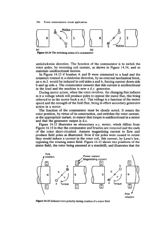
Figure 14.15 illustrates an elementary a.c. motor, which differs from
Figure 14.13 in that the commutator and brushes are removed and the ends
of the rotor short-circuited. Assume magnetising current to flow and
produce field poles as illustrated. Now if the poles were caused to rotate
they would induce a current in the rotor coil, this current, by Lenz's law,
opposing the rotating stator field. Figure 14.15 shows two positions of the
stator field, the rotor being assumed at a standstill, and illustrates that the
Pole
f rotation Power current
b
(3' ''9
R
'
X
a Torque
Pole
rotation
Figon 14.15 Induced rotor polarity during rotation of a stator field