
Page 378 - Power Electronics Handbook
P. 378
368 Power semiconductor circuit applications
like that in a d.c. generator, in fact the only difference between the
synchronous and d.c. generator is that the commutator (rectifier) is not
present in a synchronous machine, resulting in an a.c. output. In many
synchronous machines the rotor poles are produced by a electromagnet.
The commutator in Figure 14.13 is replaced by slip rings so that the current
in coil sides a and b is unidirectional and independent of rotation.
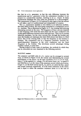
The a.c. commutator machine is very similar to an induction machine,
the stator field revolves, the rotor being connected to a commutator as in a
d.c. machine. This is illustrated in Figure 14.17, the rotating field inducing
alternating currents in the rotor. The frequency of these currents depends
on the frequency with which the stator field cuts the rotor conductors and
on the speed difference between stator field and rotor. This is as for normal
induction machines, but the rotor currents flow through the brushes and
since the brushes are stationary the stator field always cuts them at a fixed
speed, that of the rotating field, so that the frequency at the brushes is
constant. The commutator acts as a frequency converter, between the
speed-dependent frequency in the rotor conductors and the fixed
frequency at the brushes. This introduces several advantages during
machine control, as seen later.
Having looked at basic types of machines, the methods by which they
can be controlled are now examined in the following sections.
14.3.2 D.C. motors
The armature and field coils of a d.c. motor can be arranged in several
ways, as shown in Figure 14.18, the system used determining the overall
performance of the motor. In all cases equations (14.1) to (14.4) hold,
where V is the applied d.c. voltage, E is the motor back e.m.f. at speed N
and field flux 4, I,, is the value of the armature current which gives motor
torque T, If is the field current and Kf, K, and Kt are called the flux, speed
and torque constants respectively. R is the series resistance of the motor
and is equal to either the armature resistance alone or to the sum of
n
YF
B
A
Field
rotation
Figure 14.17 Elements of an a.c. commutator machine