
Page 383 - Power Electronics Handbook
P. 383
Electrical machine control 373
A.C.
supply
I'
Figure 14.22 Field control system for limited motor speed variation
field current. Generally, a field control is used only where a narrow speed
range, say 4:1, is required. This is because at high flux densities the motor
poles would saturate, whereas at low densities problems would be
experienced with motor commutation due to the predominant effect of the
armature reactance. No such restriction is placed on armature voltage-
control, and with this method drives having speed ranges of 100: 1 are quite
common.
In the discussion so far it has been assumed that the motor is being
supplied from an a.c. source, which is the usual industrial drive since an
a.c. supply is almost universally available. For many applications,
however, especially in battery vehicles, only a d.c. supply is present, and
the motor must now be driven by some form of chopper arrangement.
Most of the circuits described in Chapter 12 can be used for chopper drive
of a d.c. motor, although a few, such as the circuit shown in Figure 14.23,
are not suitable. Referring to the load voltage waveform, suppose that at
E(motor back emf)
(b)
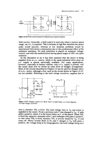
Figure 14.23 Chopper control of a shunt motor on light loads: (a) circuit diagram;
(b) load-voltage waveform
time to thyristor TH1 is fired. The load voltage rises to VB and power is
supplied to the motor. From a previous cycle C was charged to VB-E with
plate a positive, where E is the motor back e.m.f. at this speed. When THI
is fired the capacitor resonates with L and recharges with plate b positive,
is
so that when TH2 is fired, thyristor TH1 reverse biased by VB-E and
turns off. Motor current flows in D2 and C charges to VB with plate a
positive, the voltage drop in D2 being ignored, the load voltage being zero