
Page 385 - Power Electronics Handbook
P. 385
Electrical machine control 375
Feedback current slqnal
1
Converter current
Converter 2
I
feedback speed siqnal
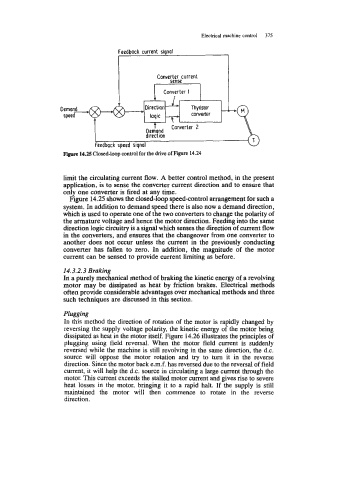
Figure 14.25 Closed-loop control for the drive of Figure 14.24
limit the circulating current flow. A better control method, in the present
application, is to sense the converter current direction and to ensure that
only one converter is fired at any time.
Figure 14.25 shows the closed-loop speed-control arrangement for such a
system. In addition to demand speed there is also now a demand direction,
which is used to operate one of the two converters to change the polarity of
the armature voltage and hence the motor direction. Feeding into the same
direction logic circuitry is a signal which senses the direction of current flow
in the converters, and ensures that the changeover from one converter to
another does not occur unless the current in the previously conducting
converter has fallen to zero. In addition, the magnitude of the motor
current can be sensed to provide current limiting as before.
14.3.2.3 Braking
In a purely mechanical method of braking the kinetic energy of a revolving
motor may be dissipated as heat by friction brakes. Electrical methods
often provide considerable advantages over mechanical methods and three
such techniques are discussed in this section.
Plugging
In this method the direction of rotation of the motor is rapidly changed by
reversing the supply voltage polarity, the kinetic energy of the motor being
dissipated as heat in the motor itself. Figure 14.26 illustrates the principles of
plugging using field reversal. When the motor field current is suddenly
reversed while the machine is still revolving in the same direction, the d.c.
source will oppose the motor rotation and try to turn it in the reverse
direction. Since the motor back e.m.f. has reversed due to the reversal of field
current, it will help the d.c. source in circulating a large current through the
motor. This current exceeds the stalled motor current and gives rise to severe
heat losses in the motor, bringing it to a rapid halt. If the supply is still
maintained the motor will then commence to rotate in the reverse
direction.