
Page 382 - Power Electronics Handbook
P. 382
312 Power semiconductor circuit applications
A
A.C. !
B
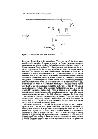
Figure 14.21 A simple half-wave series motor drive
from the description of its operation. When line A of the input goes
positive to B, capacitor C begins to charge via R1 and the motor. As soon
as the capacitor voltage reaches the breakdown value of trigger diode D4
it
breaks over and fires thyristor TH1. Load current now flows from the a.c.
supply to the motor for the remaining half cycle. When the supply polarity
reverses TH1 turns off and motor load current free-wheels in diode D1. If
the motor is heavily loaded then diode D1 forward biased for the whole
is
time that TH1 is off. This means that when C commences to charge its time
constant is determined primarily by the value of R1, the motor resistance
being small. Since the speed of a series motor varies substantially with load
this would mean that when the load decreased the motor would speed up,
even though the value of R1 remained unchanged. The load current would
now tend to go discontinuous during the half cycle, so that D1 no longer
clamps the motor voltage. This indicates that the charging time of C will be
affected by the motor back e.m.f., which is developed on residual motor
flux. Since this e.m.f. increases with speed the capacitor would take longer
to reach the trigger voltage of Dq. This effectively increases the firing delay
of the half-wave cycle and reduces the motor voltage. The motor speed will
therefore fall and remain relatively stable about the value determined by
the setting of R1. Therefore R1 represents the demand speed and motor
back e.m.f. is the feedback speed signal.
Although it is usual to control the armature voltage on a d.c. motor,
equation (14.2) shows that speed variations can also be obtained by
keeping the armature voltage fixed but changing the field voltage, and
hence flux. Figure 14.22 shows such a system where a bi-directional
converter is used to supply the field. This has the advantage of being
capable of regenerating the highly inductive current stored in the field back
to the supply. This facility is often required in fast response drives, such as
in Ward-Leonard schemes with power electronic control of the generator