
Page 386 - Power Electronics Handbook
P. 386
376 Power semiconductor circuit applications
c r
*-A *bB
-- --
-
-
+
+
--
-
-
"B "El
a. B **A
- -
(a) (b)
Figwe 14.26 Plugging in a d.c. motor: (a) motoring; (b) braking
The dual converter system shown in Figure 14.24 can readily be
extended to plugging. Suppose converter 1 was on and the motor was
rotating in the forward direction, the motor back e.m.f. being as shown. To
plug the machine converter 1 is switched off and converter 2 operated such
that the converter voltage aids the motor back e.m.f. in circulating a large
current through it. The converter firing angle delay should not exceed 90"
since regeneration would then occur, as explained below. Controlled
plugging is clearly possible by varying the delay angle, it being greatest at ci
= 0".
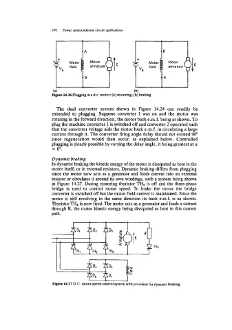
Dynamic braking
In dynamic braking the kinetic energy of the motor is dissipated as heat in the
motor itself, or in external resistors. Dynamic braking differs from plugging
since the motor now acts as a generator and feeds current into an external
resistor or circulates it around its own windings, such a system being shown
in Figure 14.27. During motoring thyristor TH, is off and the three-phase
bridge is used to control motor speed. To brake the motor the bridge
converter is switched off but the motor field current is maintained. Since the
motor is still revolving in the same direction its back e.m.f. is as shown.
Thyristor TH, is now fired. The motor acts as a generator and feeds a current
through R, the motor kinetic energy being dissipated as heat in this current
path.
Figure 14.27 D.C. motor speed-control system with provision for dynamic braking