
Page 391 - Power Electronics Handbook
P. 391
380 Power semiconductor circuit applications
plugging, on the other hand, the motor direction can be reversed if
necessary so that it is effective right down to standstill. For quick-response
systems it is therefore clearly the preferred method. A system such as that
shown in Figure 14.24 is advantageous since regeneration can be used at
higher motor speeds and then the firing angle advanced to below 90" in
order to plug the motor to rest.
14.3.2.4 Smart power control
Much of the control circuitry used for motor control is available in the form
of integrated circuits. For low power applications the power semiconductors
may also be incorporated on the same silicon chip, or in the same package as
the control circuit, to form smart power controllers (Emerald, 1996).
An example of a commercially available device is shown in Figure 14.30.
Power DMOS transistors TR, to l'R, form an H-bridge driver for the motor,
which is connected to terminals A and B. These transistors are operated in
pairs, TR, and TR2 forming one pair and TR3 and l'R, the other pair. Only
one pair of transistors operate for any given direction of rotation and the
speed of the motor is controlled by pulse width modulation, so as to vary the
voltage on the motor.
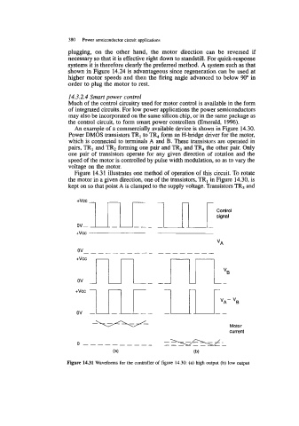
Figure 14.31 illustrates one method of operation of this circuit. To rotate
the motor in a given direction, one of the transistors, TR, in Figure 14.30, is
kept on so that point A is clamped to the supply voltage. Transistors TR, and
+VCC
+vcc
ov m- 1IIVE
Motor
current
0 -_-- - -____
(a) (b)
Figure 14.31 Waveforms for the controller of figure 14.30: (a) high output (b) low output