
Page 387 - Power Electronics Handbook
P. 387
Electrical machine control 377
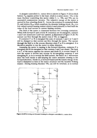
A chopper-controlled d.c. motor drive is shown in Figure 14.28 in which
battery VB supplies power to the load, which is a series motor. TH1 is the
main thyristor controlling this motor whilst C, L, TH2 and TH3 are its
associated commutation circuitry. The inductive energy of the motor is
carried by free-wheeling diode D1. Across the armature is connected diode
D2 and resistor RDB which constitute the dynamic braking circuit. RCL is a
low-valued current-sensing resistor which is used primarily to feed back the
value of the load current to current limiting circuitry.
The field of the motor is connected between two reversing contactors.
When both forward F and reverse R contactors are de-energised, contacts
1 and 3 are closed and 2 and 4 are opened, as illustrated in Figure 14.28. No
current can flow through the motor even if THI is triggered.
If contactor F or R is energised the state of contacts 1 and 2 or 3 and 4
will be changed so that current can flow through the motor. The current
through the field is in the reverse direction when F or R is energised. It is
therefore possible to run the motor in either direction.
Assuming the motor is running in the forward direction, contactor F is
energised and R de-energised so that contacts 3 and 2 are closed. The back
e.m.f. of the motor opposes the current and diode D2 is reverse biased. If
now the motor is thrown into reverse by de-energising contactor F and
energising R, so as to reverse the field current, the back e.m.f. will reverse
since the load inertia is still keeping the motor armature rotating in the
forward direction. Diode D2 is forward biased and the kinetic energy of the
load is dissipated as heat in the motor armature and the dynamic braking
resistor. During braking thyristor THI can still be switched, as in normal
14.28 Reversing and dynamic braking in a chopper-controlled d.c. motor drive