
Page 384 - Power Electronics Handbook
P. 384
374 Power semiconductor circuit applications
as at f2. On light loads the inductive load current will decay to zero, the
current flowing against the motor back e.m.f., before TH1 is refired. When
this occurs, say at f3, the capacitor will discharge through D1 and its voltage
will fall to VB-E. The motor back e.m.f. has therefore had two effects.
First, it has distorted the load voltage waveform between heavy loads and
light loads. Since the magnitude of the load voltage is determined by its
waveform this means a change in the motor voltage and hence its speed,
even though the firing period of the thyristors has been unaltered. This is
not serious and can be compensated for by using closed-loop speed control,
as in Figure 14.19. A much more serious effect of the back e.m.f. has been
a reduction in the available thyristor commutation voltage, and although
this voltage is reduced most on light loads, when commutation is least
demanding, it is a disadvantage of this circuit. A much better solution is to
replace D1 by a thyristor, which turns off as soon as capacitor resonance
has been completed, and so prevents the motor back e.m.f. from affecting
the capacitor voltage.
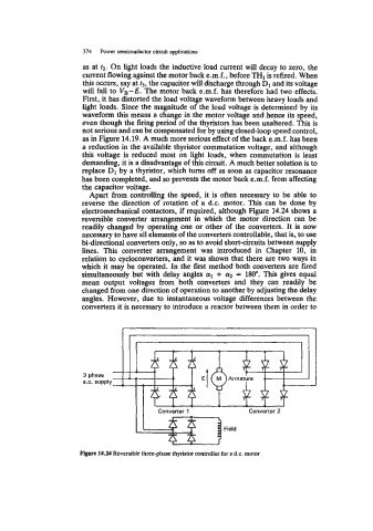
Apart from controlling the speed, it is often necessary to be able to
reverse the direction of rotation of a d.c. motor. This can be done by
electromechanical contactors, if required, although Figure 14.24 shows a
reversible converter arrangement in which the motor direction can be
readily changed by operating one or other of the converters. It is now
necessary to have all elements of the converters controllable, that is, to use
bi-directional converters only, so as to avoid short-circuits between supply
lines. This converter arrangement was introduced in Chapter 10, in
relation to cycloconverters, and it was shown that there are two ways in
which it may be operated. In the first method both converters are fired
simultaneously but with delay angles a1 + a2 = 180". This gives equal
mean output voltages from both converters and they can readily be
changed from one direction of operation to another by adjusting the delay
angles. However, due to instantaneous voltage differences between the
converters it is necessary to introduce a reactor between them in order to
3 phase
a.c. supply
Field
Fignre 14.24 Reversible three-phase thyristor controller for a d.c. motor