
Page 380 - Power Electronics Handbook
P. 380
370 Power semiconductor circuit applications
starting current would give a good motor-starting torque, and this is one of
the advantages of a d.c. motor, although excessive currents can cause
machine damage over a period of time and should be avoided. For large
motors the peak current drawn at starting is also limited by the supply
authorities, in order to prevent reductions in the voltage of the supply to
other consumers. Since the armature current is proportional to the
difference between supply voltage and motor back e.m.f. and inversely
proportional to the armature resistance, there are two methods which may
be used to limit motor-starting current. In one technique an external
resistance can be connected in series with the armature to increase the
effective armature resistance. As the motor speeds up the resistance is
progressively reduced, either manually or by automatic methods such as
servo-driven potentiometers. This is the system most commonly used with
conventional d.c. motor starters. With power electronic drives it is much
easier to arrange for the supply voltage to the motor to be progressively
increased as the machine speeds up, so that the peak armature current is
held at a predetermined value which would give good starting torque and
long motor life. Depending on whether the motor is supplied from an a.c.
or d.c. source, it is now possible to use a variety of power electronic circuits
to give controlled rectification (Chapter 9) or d.c. line control (Chapter 12)
respectively. Static contactors have also been discussed in Chapter 8.
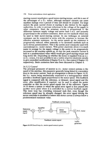
14.3.2.2 Control
The principal parameter of interest in d.c. motor control systems is the
speed of the machine, this parameter generally being linked in a secondary
loop to the motor current. Such an arrangement is shown in Figure 14.19,
the d.c. motor being mechanically connected to a tachogenerator which
provides a feedback signal proportional to the motor speed. This feedback
signal is compared with the reference, or demand, speed signal and the
error, after amplification if required, can be used to adjust the motor
controller so that the motor speed equals that of the reference. Figure
14.19 shows a system in which the speed error signal is first passed into
another servo point where it is controlled by a current feedback signal.
This inner loop has ovemding command such that, even though the
reference speed may be abruptly changed, the error signal driving the
motor controller is modified to ensure that motor current is always below a
predetermined maximum value.
Amplifier
Reference Motor
speed +E-@- controller
signal