
Page 381 - Power Electronics Handbook
P. 381
Electrical machine control 371
Although a tachogenerator has been shown in Figure 14.19 as providing
the feedback speed signal, it is not the only system that can be used. For
instance, equations (14.1) and (14.2) indicate that the motor speed is
proportional to the supply voltage provided allowance is made for the drop
in the motor armature resistance. Since this resistance can be measured, all
that is required is a knowledge of the armature current at any supply
voltage. Therefore the feedback speed signal can be made proportional to
the supply voltage on which is superimposed an I,R drop compensation
signal. Since this signal is proportional to armature current it may also be
used in the current limit loop if required.
For a certain load torque, motor speed will be such that the resultant
current interacting with the field will give a machine torque just sufficient
to overcome the load, plus internal losses. Speed control is therefore a
form of torque control. In a d.c. motor, if the armature voltage is reduced,
but the load torque kept constant, speed will fall so that the back e.m.f.
reduces sufficiently to increase the current to almost its original value (flux
being kept constant) and give an unchanged machine torque. Similarly, a
reduction in field flux would cause a reduction in speed so that the
increased current can give the same torque, the flux-current product
tending to be maintained constant. If the load torque was allowed to fall as
flux decreased, motor speed would increase to compensate for lost torque
and so keep the power constant.
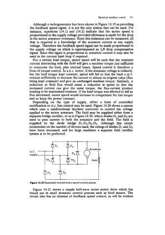
Depending on the type of supply, either a form of controlled
rectification or d.c. line control may be used. Figure 14.20 shows a system
which uses a unidirectional thyristor converter to control the voltage
applied to the motor armature. The field may be supplied either from a
separate bridge rectifier, or as in Figure 14.20, where diodes D1 and D2 are
used to pass current to both the armature and the field. The field is
supplied by the diode bridge D~-D~-D~-Ds. Although this circuit
economises on the number of devices used, the ratings of diodes D1 and D2
have been increased, and for large machines a separate field rectifier
system is to be preferred.
Figure 14.20 Separately excited motor speed-control system
Figure 14.21 shows a simple half-wave series motor drive which has
found use in small domestic control systems such as food mixers. The
circuit also has an element of feedback speed control, as will be evident