
Page 379 - Power Electronics Handbook
P. 379
d.c. !r%3 LL 369
Electrical machine control
d,c,
.-
(d) d.c. supply 33
Armature 71 ($ 1:; supply a supply Series field
L
a
(a)
(b)
supply Field supply
.c
m
(C)
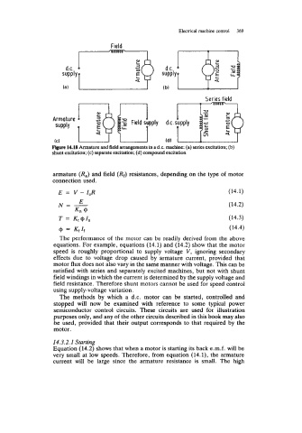
Figure 14.18 Armature and field arrangements in a d.c. machine: (a) series excitation; (b)
shunt excitation; (c) separate excitation; (d) compound excitation
armature (R,) and field (Rf) resistances, depending on the type of motor
connection used.
E = V - I,R (14.1)
(14.2)
T = Kt@I, (14.3)
@ = Kf1f (14.4)
The performance of the motor can be readily derived from the above
equations. For example, equations (14.1) and (14.2) show that the motor
speed is roughly proportional to supply voltage V, ignoring secondary
effects due to voltage drop caused by armature current, provided that
motor flux does not also vary in the same manner with voltage. This can be
satisfied with series and separately excited machines, but not with shunt
field windings in which the current is determined by the supply voltage and
field resistance. Therefore shunt motors cannot be used for speed control
using supply-voltage variation.
The methods by which a d.c. motor can be started, controlled and
stopped will now be examined with reference to some typical power
semiconductor control circuits. These circuits are used for illustration
purposes only, and any of the other circuits described in this book may also
be used, provided that their output corresponds to that required by the
motor.
14.3.2.1 Starting
Equation (14.2) shows that when a motor is starting its back e.m.f. will be
very small at low speeds. Therefore, from equation (14.1), the armature
current will be large since the armature resistance is small. The high