
Page 125 - Power Electronics Handbook
P. 125
118 Electromagnetic compatibility
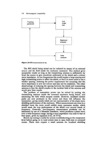
Tracking Unit
generator under
test
Figure 4.10 FtFI measurement set up
The RFI shield being tested can be radiated by means of an external
source and the field inside the enclosure measured. This method gives
acceptable results so long as the transmitting antenna is sufficiently far
from the source to give wavefront uniformity at the shield and a correct
wave impedance. At low frequencies this would require a large spacing and
high transmitting power to effect the shield, so that it is more usual to use a
smaller spacing, reducing the power requirement but accepting that the
wave impedance is now not correct and may not be consistent. The other
disadvantage of reducing the spacing between the shield and transmitting
antenna is that the shield couples to the incident field of the antenna and
would give false results.
The problem of transmitter power can be solved by putting the
transmitting antenna inside the screened enclosure being tested, and
measuring the field which escapes outside. However, localised current
paths are now produced in the screen and these will influence the
transmitter, giving results which are not representative of the plane-wave
shielding performance of the enclosure. When measurements are done in a
shielded room the room would exhibit many resonance modes, which
would mask the true performance of the shield over several bands of
frequency. Generally, low-frequency measurement problems can be
minimised by use of a Rhombic Simulator, which produces a plane wave
over a wide frequency range, having a wave impedance very near to that of
free space, given by equation (4.8), of 377 62.
Bench-top testing is useful for system troubleshooting at the component
level before going on to total system tests in open field sites or screened
rooms. These tests require a small antenna for localised shielding