
Page 124 - Power Electronics Handbook
P. 124
EMC measurement I 17
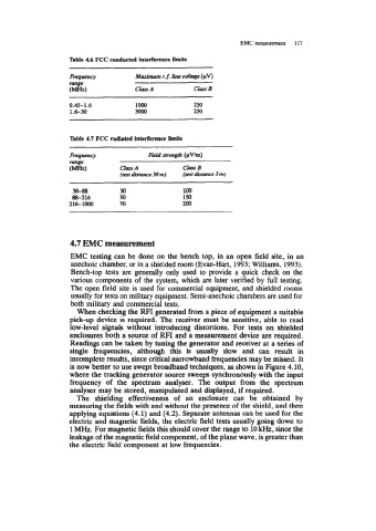
Table 4.6 FCC conducted interference Mts
Fnqwncy Maximum .f. line voltage (pV)
range
(-1 ClwA C&s B
0.45-1.6 lo00 250
1.6-30 3am 250
Table 4.7 FCC rndiated interference limits
FrcqrcLncy Field strength (pV/m)
i=1 ChA clw B
(test distance 30 m) (test distance 3 m)
30-88 30 100
88-216 50 150
216-1000 70 200
4.7 EMC measurement
EMC testing can be done on the bench top, in an open field site, in an
anechoic chamber, or in a shielded room (Evan-Hart, 1993; Williams, 1993).
Bench-top tests are generally only used to provide a quick check on the
various components of the system, which are later verified by full testing.
The open field site is used for commercial equipment, and shielded rooms
usually for tests on military equipment. Semi-anechoic chambers are used for
both military and commercial tests.
When checking the RFI generated from a piece of equipment a suitable
pick-up device is required. The receiver must be sensitive, able to read
low-level signals without introducing distortions. For tests on shielded
enclosures both a source of RFI and a measurement device are required.
Readings can be taken by tuning the generator and receiver at a series of
single frequencies, although this is usually slow and can result in
incomplete results, since critical narrowband frequencies may be missed. It
is now better to use swept broadband techniques, as shown in Figure 4.10,
where the tracking generator source sweeps synchronously with the input
frequency of the spectrum analyser. The output from the spectrum
analyser may be stored, manipulated and displayed, if required.
The shielding effectiveness of an enclosure can be obtained by
measuring the fields with and without the presence of the shield, and then
applying equations (4.1) and (4.2). Separate antennas can be used for the
electric and magnetic fields, the electric field tests usually going down to
1 MHz. For magnetic fields this should cover the range to 10 kHz, since the
leakage of the magnetic field component, of the plane wave, is greater than
the electric field component at low frequencies.