
Page 119 - Power Electronics Handbook
P. 119
112 Electromagnetic compatibility
4.5.3 conducted EMI shielding
Protection against EM1 being transmitted along a cable is achieved by
means of suppression filters, which consist basically of inductive and
capacitive elements. A variety of such filters exist since a type which
suppresses interference completely from one system may be quite useless
in another. The location of the filter is also important, and it should
generally be placed directly at the source of interference, and the output
and input leads should never be bundled together.
L-type -+'%
L-type
c, %type %-type
T'1 ' T-type T-type
Low pass High pass
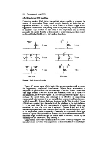
Figure 4.7 Basic Uter configuration
Figure 4.7 shows some of the basic filter arrangements which are used
for suppressing conducted interference. Where large attenuation is
required it is preferable to use several stages of smaller filters, rather than
one large system. Low-pass filters are commonly used in a variety of
modifications, as shown in Figure 4.8. The arrangement of Figure 4.8(a) is
perhaps the most basic, and although it is effective in suppressing
symmetrical interference it is not suitable for asymmetrical interference,
which is caused by leakage between Lines and earth. The circuit of Figure
4.8(b) is now used, where the polarity of the windings in the split inductor
L1b are such that the d.c. components of current through them are
cancelled, so that the core size is reduced. Figures 4.8(c) and 4.8(d)
introduce progressively more attenuation into the interfering signal path,
at the expense of greater complexity. Generally, arrangements of the type
shown in Figure 4.8(d) should not be used if & is a semiconductor switch,
since the surge current through the switch when it turns on, caused by the
discharge of the capacitors, may destroy it.
Components chosen for the filters should also be carefully designed. The
inductors must have low stray capacitors, so they should not be multilayer,