
Page 310 - Power Electronics Handbook
P. 310
300 D.C. link frequency changers
Figure 13.16 Parallel capacitor-inductor
cornmutation in a bridge inverter with tapped
Load supply
Three phase load
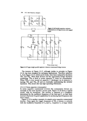
Flyre 13.17 Light-weight parallel capacitor-inductor commutated bridge inverter
The inverter of Figure 13.17, although similar in principle to Figure
13.14, has been designed for aerospace applications. Therefore inductors
LI from Figure 13.14, which can be bulky, have been replaced by thyristors
TH7 and TH8. With these devices and the appropriate bridge thyristors
conducting, TH9 is fired to prime capacitor C ready for commutation.
When THIO is now turned on capacitor C discharges via its inductor L,
turning TH, and TH, off and so eventually commutating the inverter
thyristors. This circuit also has high operating efficiencies.
13.2.3.3 Series capacitor commutation
In series capacitor commutated inverters the commutation devices are
normally in the main thyristor current path. Figure 13.18 shows a typical
circuit, with its waveforms. The inverter is operated at a frequency
determined by the oscillatory frequency of the load and C, so that these
inverters find most frequent application for producing fixed frequency sine
wave output.
Figure 13.19 is another example of a simple series capacitor commutated
inverter. Once again the trigger frequency of TH1 is chosen to coincide
with the oscillatory frequency of C, and L1. Capacitor C1 is large valued