
Page 305 - Power Electronics Handbook
P. 305
Inverter circuits 295
+"B
1
1
T
1 I J
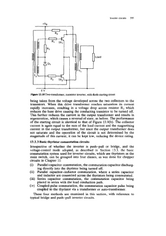
VWU~~ v~nr.4 IIVM~ sur v~a~abr urvr~vywu abavaa LIIC rnw CW~I~LLWLJ LV Liic
transistors. When this drive transformer reaches saturation its current
rapidly increases, resulting in a voltage drop across resistor R3 which
reduces the base drive causing the conducting transistor to be turned off.
This further reduces the current in the output transformer and results in
regeneration, which causes a reversal of state, as before. The performance
of the starting circuit is identical to that of Figure 13.9(b). The collector
current is again equal to the sum of the load current and the magnetising
current in the output transformer, but since the output transformer does
not saturate and the operation of the circuit is not determined by the
magnitude of this current, it can be kept low, reducing the device rating.
Irrespective of whether the inverter is push-pull or bridge, and the
voltage-control mode adopted, as described in Section 13.3, the basic
commutation system used for inverter circuits, which use thyristors as the
main switch, can be grouped into four classes, as was done for chopper
circuits in Chapter 11:
(i) Parallel-capacitor commutation, the commutation capacitor discharg-
ing directly into the thyristor being turned off.
(ii) Parallel capacitor-inductor commutation, where a series capacitor
and inductor are connected across the thyristors being commutated.
(iii) Series capacitor commutation, the commutation capacitor being
placed in series with the load conduction path.
(iv) Coupled-pulse cornmutation, the commutation capacitor pulse being
coupled to the thyristor via a transformer or auto-transformer.
VI" ..." ....
There fniir methndc are eramined in thic certinn with rmCnrnnen tn
1"IW'w.'-
"
11.
6"
..1.1.
"WW.."ll,
.
a
.
.
,
.vu.
X"..
... ""I I..-...
.I.-"
typical bridge and push-pull inverter circuits.