
Page 302 - Power Electronics Handbook
P. 302
292 D.C. link frequency changers
+"B
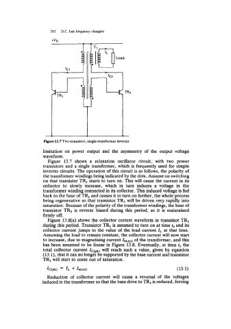
Figure 13.7 Two-transistor , single-transformer inverter
limitation on power output and the asymmetry of the output voltage
waveform.
Figure 13.7 shows a relaxation oscillator circuit, with two power
transistors and a single transformer, which is frequently used for simple
inverter circuits. The operation of this circuit is as follows, the polarity of
the transformer windings being indicated by the dots. Assume on switching
on that transistor TRI starts to turn on. This will cause the current in its
collector to slowly increase, which in turn induces a voltage in the
transformer winding connected in its collector. This induced voltage is fed
back to the base of TRI and causes it to turn on further, the whole process
being regenerative so that transistor TRI will be driven very rapidly into
saturation. Because of the polarity of the transformer windings, the base of
transistor TR2 is reverse biased during this period, so it is maintained
firmly off.
Figure 13.8(a) shows the collector current waveform in transistor TR1
during this period. Transistor TRI is assumed to turn on at time to and its
collector current jumps to the value of the load current ZL at that time.
Assuming the load to remain constant, the collector current will now start
to increase, due to magnetising current ZMAG of the transformer, and this
has been assumed to be linear in Figure 13.8. Eventually, at time tl the
total collector current Ic(pk) will reach such a value, given by equation
(13.1), that it can no longer be supported by the base current and transistor
TR1 will start to come out of saturation.
IC(pk) = IL -k IMAG (13.1)
Reduction of collector current will cause a reversal of the voltages
induced in the transformer so that the base drive to TRI is reduced, forcing