
Page 300 - Power Electronics Handbook
P. 300
290 D.C. link frequency changers
transistors TR1 and T& are turned on and conduct since the current is
starting positive. At time tl transistor T& is turned off. The load current
continues to circulate through transistor TR1 and diode D3, effectively
short circuiting the load. At t2 transistor TRI is turned off and TR2 and TR3
are turned on, causing the load current to reverse. Finally, at time r3
transistor TR3 is turned off and load current circulates through TR2 and
D4, the load voltage again being zero. As seen from Figure 13.4(b), the
mean load voltage has been reduced over that of Figure 13.4(a).
A common requirement in frequency changers is that of regeneration.
For instance, a variable-frequency motor control, in, for example, a
locomotive, will regenerate when it starts to move downhill and the motor
acts as a generator. Regeneration can be obtained in inverters although it is
not a natural phenomenon of most inverter systems, as was the case for
cycloconverters, and special modifications are necessary to accomplish it
successfully. Unless the d.c. supply is 'soft' the regenerated energy will
cause excessive voltage increase in the system. For inverters operating
from a rectified a.c. source, it is necessary to connect an inverting bridge to
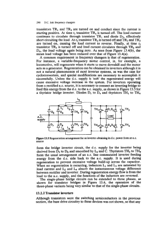
feed this energy from the d.c. to the a.c. supply, as shown in Figure 13.5 for
a thyristor bridge inverter. Diodes D, to D4 and thyristors THI to TI&
L,
I J
Flgnre 13.5 Regeneration arrangement for an inverter obtaining its d.c. power from an a.c.
source
form the bridge inverter circuit, the d.c. supply for the inverter being
derived from Ds to D8 and smoothed by and C. Thyristors TH, to THE
form the usual arrangement of an a.c. line commutated inverter feeding
energy from the d.c. side back to the a.c. supply. It is used during
regeneration to prevent excessive voltage build-up across the capacitor.
When no regeneration is occurring, inductors L1 and are saturated by
load current and LQ and L4 absorb the instantaneous voltage difference
between rectifier and inverter. During regeneration energy flow is from the
load to the ax. supply, and the functions of the inductors are reversed.
The single-phase bridge circuits can be extended to three phases, as
shown for transistor bridges in Figure 13.6, the operation of the
three-phase variants being very similar to that of the single-phase circuits.
13.2.2 Transistor inverters
Although transistors were the switching semiconductors in the previous
section, the base drive circuitry to these devices was not shown, so that any