
Page 296 - Power Electronics Handbook
P. 296
286 D.C. link frequency changers
13.2.1 Inverter configurations
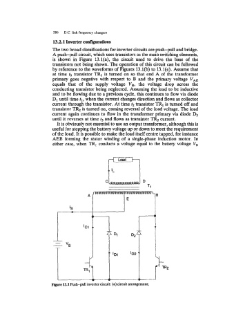
The two broad classifications for inverter circuits are push-pull and bridge.
A push-pull circuit, which uses transistors as the main switching elements,
is shown in Figure 13.1(a), the circuit used to drive the base of the
transistors not being shown. The operation of this circuit can be followed
by reference to the waveforms of Figures 13.l(b) to 13.1(e). Assume that
at time to transistor TRl is turned on so that end A of the transformer
primary goes negative with respect to B and the primary voltage V,
equals that of the supply voltage V,, the voltage drop across the
conducting transistor being neglected. Assuming the load to be inductive
and to be flowing due to a previous cycle, this continues to flow via diode
D1 until time tl, when the current changes direction and flows as collector
current through the transistor. At time f2 transistor TR1 is turned off and
transistor TR2 is turned on, causing reversal of the load voltage. The load
current again continues to flow in the transformer primary via diode D2
until it reverses at time t3 and flows as transistor TR2 current.
It is obviously not essential to use an output transformer, although this is
useful for stepping the battery voltage up or down to meet the requirement
of the load. It is possible to make the load itself centre tapped, for instance
AEB forming the stator winding of a single-phase induction motor. In
either case, when TR, conducts a voltage equal to the battery voltage V,
A 3
'S
L
Figure 13.1 Push-pull inverter circuit: (a) circuit arrangement;