
Page 293 - Power Electronics Handbook
P. 293
Chopper control circuits 283
Power
switches -
L ' I
generator
Variable
pedestal
Voltage detect
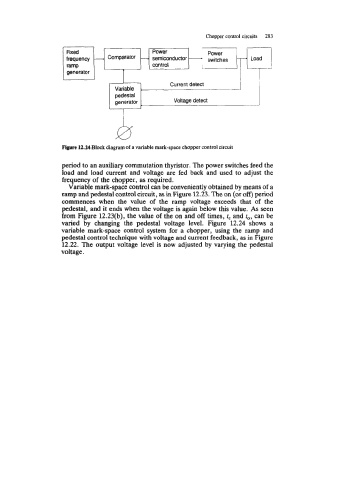
Figure 12.24 Block diagram of a variable mark-space chopper control circuit
period to an auxiliary commutation thyristor. The power switches feed the
load and load current and voltage are fed back and used to adjust the
frequency of the chopper, as required.
Variable mark-space control can be conveniently obtained by means of a
ramp and pedestal control circuit, as in Figure 12.23. The on (or off) period
commences when the value of the ramp voltage exceeds that of the
pedestal, and it ends when the voltage is again below this value. As seen
from Figure 12.23(b), the value of the on and off times, rc and to, can be
varied by changing the pedestal voltage level. Figure 12.24 shows a
variable mark-space control system for a chopper, using the ramp and
pedestal control technique with voltage and current feedback, as in Figure
12.22. The output voltage level is now adjusted by varying the pedestal
voltage.