
Page 290 - Power Electronics Handbook
P. 290
280 D.C. to d.c. converters
Thyristor TH2 carries a current of during the charge period of C
only, so that its mean current is given by equation (12.22), although its size
is normally determined by its peak current capability of 1, k). Similarly,
thyristor TH3 has a mean rating given by equation (12.28) but a peak
resonant current of equation (12.22), which can be high. The value of C is
fixed by the commutation requirements of equation (12.23), where tom is
the turn-off time of the main thyristor, and inductor L1 is chosen such that
the resonant time, given by equation (2.4), is small compared to the
operating frequency, usually between 5% and 10%.
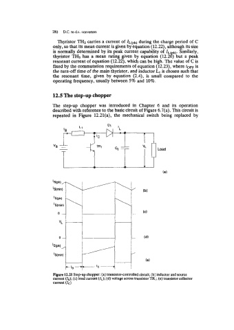
12.5 The step-up chopper
The step-up chopper was introduced in Chapter 6 and its operation
described with reference to the basic circuit of Figure 6.7(a). This circuit is
repeated in Figure 12.21(a), the mechanical switch being replaced by
L Load
Figure 12.21 Step-up chopper: (a) transistor-controlled circuit; (b) inductor and source
current (Is); (c) load current (IL); (d) voltage across transistor TR,; (e) transistor collector
current (Ic)