
Page 287 - Power Electronics Handbook
P. 287
Design of chopper circuits 277
(12.17)
The mean load current is given by equation (12.18).
(12.18)
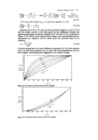
Equations (12.15) to (12.18) are shown plotted in Figures 12.16 to 12.19
and the ripple current in the load, given by the difference between the
minimum and peak currents in equations (12.14) and (12.15), is plotted in
Figure 12.20. These curves allow device ratings at any operating frequency,
determined by equation (12.19) which gives the periodic time, to be
obtained.
(tc + to)
T= (12.19)
LIR
All these graphs have the ratio k defined in equation (12.12) as the abscissa
since, as seen from equation (12.1), this is the most fundamental ratio in
the chopper, determining the magnitude of its output voltage.
>.I>-
+
t,+l,
Figure 12.16 Variation of peak load current in a chopper
IC
lC+lO
Figure 12.17 Variation of main switch current in a choppcr