
Page 286 - Power Electronics Handbook
P. 286
276 D.C. to d.c. converters
I
I
I
I
L- tc -1
to-
I I
I I 1
Time
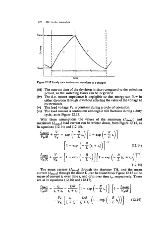
Fil[lue 12.15 Steady state load current waveform of a chopper
(iii) The turn-on time of the thyristors is short compared to the switching
period, so the switching losses can be neglected.
(iv) The d.c. source impedance is negligible so that energy can flow in
either direction through it without affecting the value of the voltage at
its terminals.
(v) The load voltage VL is constant during a cycle of operation.
(vi) The load current is continuous although it will fluctuate during a duty
cycle, as in Figure 12.15.
With these assumptions the values of the minimum and
maximum (IL@k)) load current can be written down, from Figure 12.15, as
in equations (12.14) and (12.15).
v
R
IL(min) + - exp (- ro) [ 1 - exp (- R rc)]
=
VBIR VB
(12.14)
(12.15)
The mean current (IT(av)) through the thyristor THl and the mean
current through the diode D1 can be found from Figure 12.15 as the
mean of current il over time rc and of i2 over time to, respectively. These
are as in equations (12.16) and (12.17).
-=--- rC LIR p-exp(-:tc)] [I-+]
zT(av)
V$R t, + ro tc + to