
Page 283 - Power Electronics Handbook
P. 283
D.C. to d.c. converter circuits 273
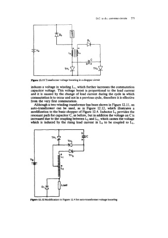
Flrprr 12.11 Transformer voltage boosting in a chopper circuit
induces a voltage in winding L1, which further increases the commutation
capacitor voltage. This voltage boost is proportional to the load current
and it is caused by the change of load current during the cycle in which
commutation is to occur and not in a previous cycle, therefore it is effective
from the very first commutation.
Although a two-winding transformer has beem shown in Figure 12.11, an
auto-transformer can be used, as in Figure 12.12, which illustrates a
modification to the basic chopper of Figure 12.4. Inductor L1 provides the
resonant path for capacitor C, as before, but in addition the voltage on C is
increased due to the coupling between and L1, which causes the voltage
which is induced by the rising load current in to be coupled to L1,
pbprc 12.12 Modification to Figure 12.4 for auto-transformer voltage boosting